contact number:
+86-532-86896691

-

Market Activity
Lightwave Component Analyzer for Testing of Electro-Optical Components
 2022-10-26

The 6433 series Lightwave Component Analyzer integrate 4 test modes: E/E measurement mode, E/O measurement mode, O/E measurement mode and O/O measurement mode, with various display format such as logarithmic amplitude, linear amplitude, phase, group delay, Smith chart, polar coordinates, equipped with multiple standard interfaces such as USB, LAN, GPIB, VGA, etc., The product can accurately measure the amplitude-frequency characteristics, phase-frequency characteristics and group delay characteristics of the optoelectronic network.
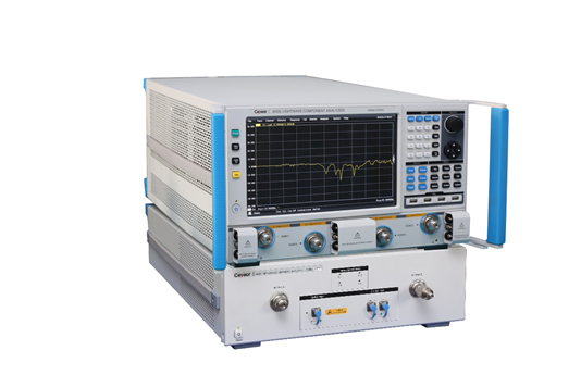
Fig. 1 6433 Lightwave Component Analyzer
There are 4 product models of 6433 Series Lightwave component analyzer-6433D (10MHz to 20GHz), 6433F (10MHz to 43.5GHz), 6433H (10MHz to 50GHz) and 6433L (10MHz to 67GHz), they can be divided into 2-port and 4-port models. The Lightwave Component Analyzer is mainly used in high-speed broadband electro-optical device (electro-optical modulator, direct-adjusted laser, TOSA), optoelectronic device (PD, PIN, APD, ROSA), optical device (optical attenuator, EDFA) frequency response parameter test. It is an efficient test equipment in the scientific research, production and measurement process of optical chips, optical devices, optical transceiver components, optoelectronic instruments, and optical communication systems.
Integrated multi-function test wizard
The 6433 series Lightwave Component Analyzers have 4 measurement modes: electric-electric, electric-optical, optical-electric and optical-optical. The function modes can be switched arbitrarily, which can meet the measurement requirements of S-parameter, impedance, time domain and other parameters of most common devices at present. The integrated parameter setting is convenient for users to quickly complete the setting of light wave parameters, optical path de-embedding parameters, radio frequency de-embedding parameters and one-key testing.
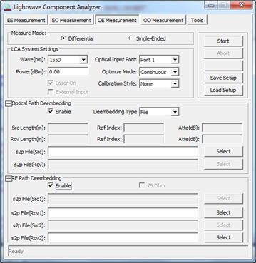
Fig.1 Function measurement interface
One-click fast frequency sweep test
The 6433 series Lightwave Component Analyzer adopts the integrated design scheme of microwave module and lightwave module to build a high-precision optoelectronic network error model, and uses core calibration algorithms to realize one-key broadband fast sweep test of E/O, O/E and O/O devices. For the S11 and S21 parameters test of electro-optical devices such as electro-optical modulators and directly modulated lasers, the multi-window display can quickly obtain the reflection and transmission characteristics of each frequency point of the test object, for photoelectric devices such as photodetectors, ROSA, TIA integrated components, etc. The S22 and S21 parameters test can use the cursor function to quickly analyze the 3dB bandwidth and evaluate the frequency response characteristics of the device, for the S21 parameter test of optical devices such as fiber filters, it can quickly achieve the measurement of loss, flatness and other indicators.
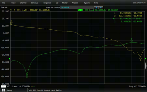
Fig.2 Device S21 and S22 Parameter Measurement
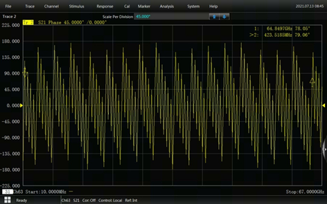
Fig.3 Device Phase Measurement
Balanced device test
The 6433 series Lightwave component analyzers can be equipped with a 4-port model to achieve the test requirements of balanced optical transmitters or optical receivers for differential gain and common mode rejection parameters, which is more suitable for the measurement occasions of multi-port parameters in the current and future high-speed optical fiber communication fields.

Fig.4 Balanced ROSA Device Connection and Mixed S-parameters
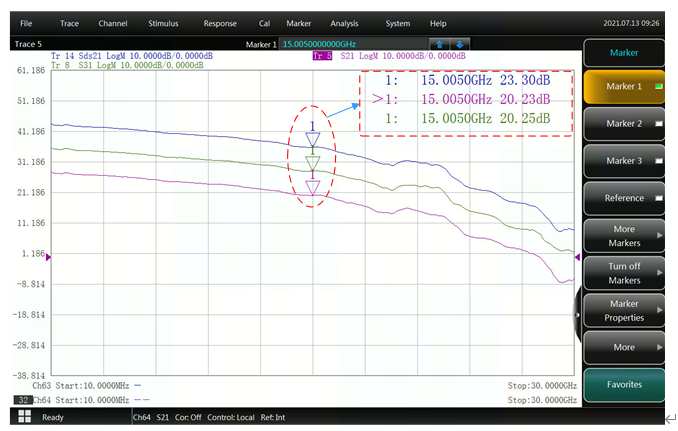
Fig.5 Balanced ROSA Measurement
Flexible Calibration Method and Calibration Kits
The 6433 series Lightwave component analyzers provide multiple calibration types such as guided calibration, unguided calibration, and electrical calibration. Various calibration components such as coaxial mechanical calibration components or electronic calibration components can be selected according to actual test needs to facilitate the testing of devices of different interface types.
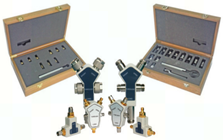
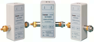
Fig.6 Mechanical Calibration Kit and E-cal
Multi-windows Display and Analysis
The 6433 series Lightwave component analyzer supports up to 64 measurement channels and 32 measurement windows. Each window can display up to 16 test traces at the same time, which can realize multi-window and multi-format display of results; high-resolution multi-touch capacitive screen can quickly realize various input and selection operations, fast and efficient, convenient for users to quickly analyze data, and provide users with a new light wave component analyzer experience.
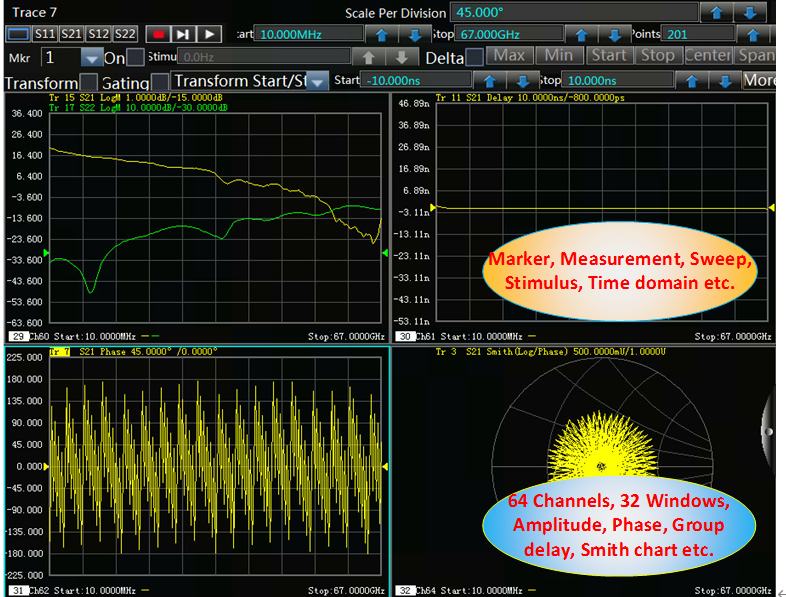
Fig.7 Multi-window Display and Analysis Measurement
Large Dynamic Range and Low Trace Noise
The 6433 series Lightwave component analyzer adopts the design concept of mixing reception, using high-precision and flat-response core components, combined with setting different intermediate frequency bandwidth and average, to obtain a larger dynamic measurement range and smaller trace noise. The concept can get more details of the measurement results to meet the user's test requirements for large dynamic range and high precision.
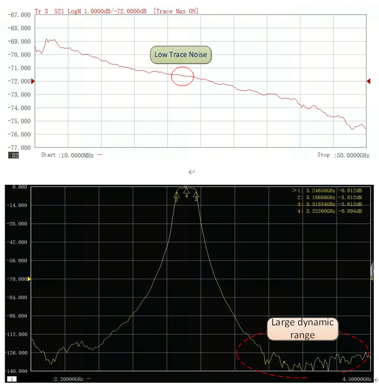
Fig.8 Trace noise and dynamic range measurement
Automatic Fixture Removal
The 6433 series Lightwave component analyzer can automatically remove the fixtures connected to the test link through optical de-embedding and radio-frequency de-embedding. When electrical fixtures or optical fixtures are introduced into the test link, users can select the enable state of radio frequency de-embedding and optical path de-embedding, import fixture parameter files, and automatically remove fixture data to improve measurement accuracy. Especially when the probe error required for the chip test is removed, the measurement is more flexible and meets the measurement needs of users in different occasions.
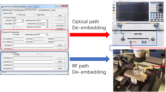
Fig.9 On-wafer measurement process
Multi-function Toolbox
The 6433 series Lightwave component analyzer has a built-in large dynamic range optical power meter, which can monitor the input optical power in real time. Through advanced settings, the optical transmitter module can be set to the polarization-maintaining laser source output mode (CW) mode, and the extinction ratio is greater than 20dB. The MZ LiNiO3 modulator provides the required polarization-maintaining light source. The test is not limited to 1310nm/1550nm, also supports external light source input from 1260nm to 1630nm, covers a wider communication wavelength, and meets the measurement requirements of the core components of CWDM and DWDM systems.
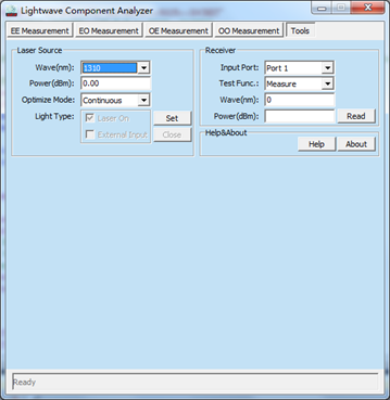
Fig.10 Multi-function toolbox


